
12 Volt Relay Wiring Diagram Free Wiring Diagram
How To Wire a 4 or 5 Pin Relay Rocky X TV 21.9K subscribers Subscribe Subscribed 6.9K Share Save 630K views 6 years ago In this video I show you how to wire a 12 volt automotive Bosch.
12V Relay Wiring Diagram 5 Pin Cadician's Blog
In this video, you'll learn about the 5-pin relays, and how they function.DIY| Controlling AC Devices by 5V Relay: https://www.youtube.com/watch?v=ulJ6kEK3F1Q
Five Pin Relay Wiring Diagram Collection
In this article 01 What is a Relay and How Does it Work? 02 Electrical Specifications of a Relay 03 Differences between 4 or 5 Pin Relays 04 Relay Wiring Diagram - Use of Relay 05 Use EdrawMax for Wiring Diagram Creation - [Free to Create] What is a Relay and How Does it Work? What is a Relay? A relay is an electronically generated switch.

5 Pin Led Flasher Relay Wiring Diagram Wiring Diagram
A 5 pin relay consists of five terminals, including an armature, normally closed contact, normally open contact, common terminal and coil. The coil is used to energize the relay, while the armature and normally closed contact are used together to control the flow of current from the battery to the light.

Dual Horn 5 Pin Relay Wiring Diagram 5 Wire Horn Diagram Electrical
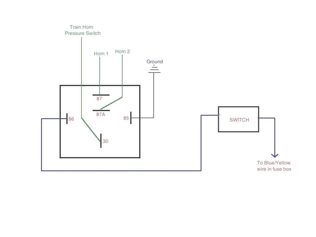
5-Pin Relay Circuit. Step 1: Connect one end of the switch to the positive power source. Step 2: Connect the other end of the switch to the coil terminal (pin 85 or pin 86) of the relay. Here it is connected to pin 85. Step 3: Connect the ground to the remaining end (pin 86 or pin 85) of the relay.

5 Pin Relay Wiring Diagram Wiring Electrical diagram, Relay
In this 5-pin relay: Pins 85 and 86 receive the trigger current. They might be marked 'COIL.' Connect either one to a switch and the other to the negative terminal of the power source. Pin 87 is connected to the device you want to control. When switched on, this terminal connects to the power source terminal inside the relay and powers the load.
5 Pin Relay Harness 40 Amp Relay Socket Online Led Store Relay
Relay Wiring Diagram | 4-Pin & 5-Pin Automotive Relay January 31, 2022 ByLeela Prasad Relays are one of the essential components of modern electrical systems. A Relayis nothing but an electromechanical switch in the sense that a mechanical contact toggles between ON and OFF states due to an electrical signal.

40 Amp Pin Relay Wiring Diagram ubicaciondepersonas.cdmx.gob.mx
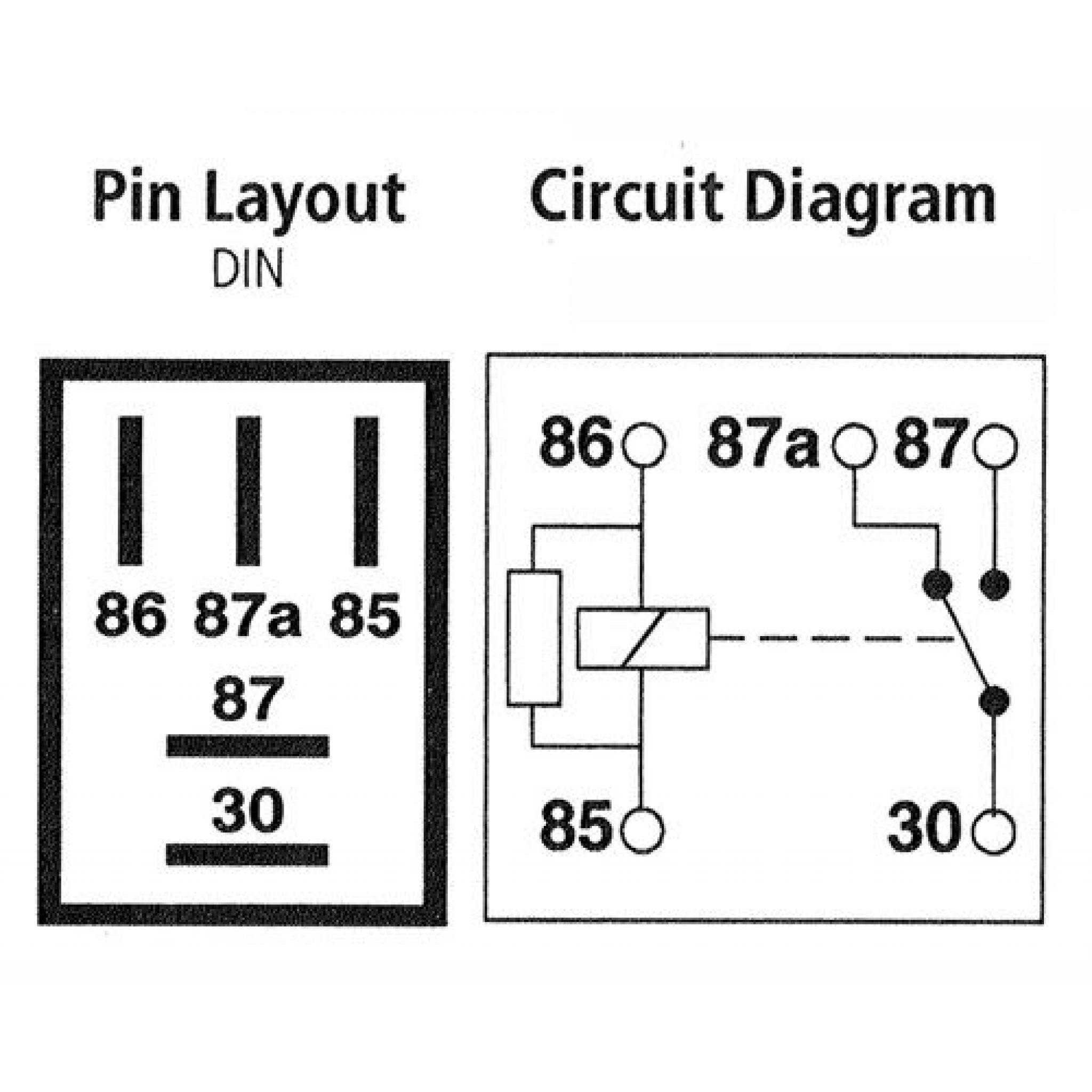
A 5-pin relay is an SPDT relay, which means that the contacts of the relay are single pole double throw. In single pole double throw relay, we have one pin is common, 2nd is normally close and 3rd is normally open. Two pins for the coil. This relay can be used for different types of controlling or switching.
5 Pin Relay Wiring Diagram Driving Lights Cadician's Blog
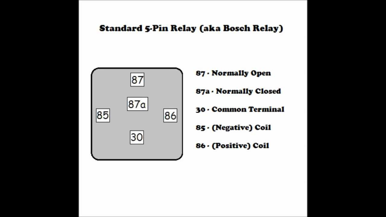
5-Pin-Relay-Wiring-Diagram-On-Relay-Case According to DIN 72552 Standard, each pin of a relay is numbered 85, 86, 30, 87, and 87a. You need to know that a relay has two circuits, a coil circuit (also called a "low current circuit", or "inductive circuit"), and a high-amperage circuit.

[DIAGRAM] 3 Pin Horn Relay Diagram Wiring Schematic FULL Version HD
A 5 pin relay is an electromagnetic switch that is commonly used in automotive applications. It is designed to control high current devices or circuits by using a lower current signal. The relay has five pins which are labeled as follows: Pin 30 - Common (C) Pin 87 - Normally Open (NO) Pin 87a - Normally Closed (NC) Pin 85 - Coil+

5 pin relay wiring diagram YouTube
how to wire a 5 pin relay. in this video I will show you how to wire a 5 pin relay.Equipment used in the filming is Gopro Hero 8 fromhttp://Gopro.comthe equi.

5 Pin Relay Wiring Diagram Use Of Relay
The 5V relay module can be used to control a load such as a lighting system motor or solenoid it can also be used to switch ac or dc voltages the maximum voltage and current that the 5V relay.
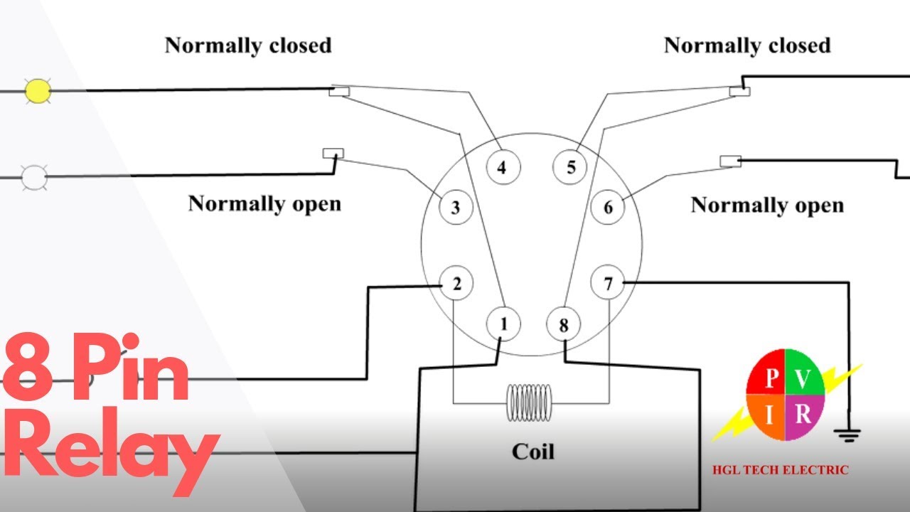
8 pin relay. Electric relay. Electric relays principles and
The 5 pin relays have silver contacts for long-lasting performance and a removable metal mounting tab for easy installation. All relays have a 500,000 cycle rating and a braided power strap for increased reliability. Available in a variety of amp ratings in 12 or 24-volt configurations, with the option of resistor or diode style circuit protection.

5 Pin Relay Wiring Diagram Fuel Pump
Creating a wiring diagram for a 5 pin relay can be a daunting task, but there are a few tips to help make the process easier. First, always use the right colors for the connections. Red is typically used for the positive side and black is used for the negative side. Additionally, try to make the labels as clear and concise as possible so they.

Relay Wiring Diagram 5 Pin Stylesync Me Fair blurts.me Automotive
To wire a 5 pin relay, you'll need the following parts: A 5 Pin Relay The correct wiring harness for the application Electrical Tape or Heat Shrink Tubing (optional) Wire Crimping Tools (optional) Important Relay Terminology Before attempting to wire a 5 pin relay, it is important to understand the following terminology and definitions:

Relay Wiring Diagram and Function Explained ETechnoG
October 17, 2023 how to wire a 5 pin relay Are you an aspiring DIY enthusiast or an automotive enthusiast looking to learn how to wire a 5 pin relay? Look no further! In this article, we will provide you with a step-by-step guide on how to wire a 5 pin relay, covering all the essential details you need to know.